|
|
|
| ||||||||||||||||
|
| |||||||||||||||||
|
APCMAN-1LP APCMAN-1LP-ZS |
|||||||||||||||||
|
Top of Page | |||||||||||||||||
|
2 Description |
|||||||||||||||||
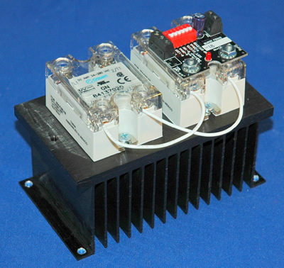
| The APCMAN-1LP is power control module designed for use with standard footprint zero cross or random fire SSRs (Solid State Relays). The module mounts directly on the SSR's input screws and derives its power from the 4-20mA command input. The module operates by burst firing the SSR's control input. The power delivered to the load is proportional to the command input signal. | |||||||||||||||||
|
2.1 Features |
|||||||||||||||||
| |||||||||||||||||
|
3 Installation |
|||||||||||||||||
Top of Page |
|||||||||||||||||
|
3.1 Mounting Instructions |
|||||||||||||||||
|
The APCMAN-1LP mounts directly to the control input terminals of an SSR. Some relays have short input screws and longer screws will be required to reach through the contacts on the APCMAN-1LP. Be sure to observe the correct polarity when mounting the module. | |||||||||||||||||
|
Top of Page |
|||||||||||||||||
|
4 Operation |
|||||||||||||||||
|
4.1 Command Input |
|||||||||||||||||
| The APCMAN-1LP can accept a 4-20mA input. If more than one APCMAN-1LP is to be used from the same drive signal, the APCMAN-1LP inputs should be connected in series. The command input is direct acting, meaning that as the input value increases, the control output increases in direct proportion. | |||||||||||||||||
|
4.1.1 Input Fail-Safe Protection |
|||||||||||||||||
| If the signal sent to the APCMAN-1LP's command input should become electrically open, the module's output will be forced to an off state since power will be lost. | |||||||||||||||||
|
4.2 Control Output |
|||||||||||||||||
| The APCMAN-1LP's SSR output drive is a DC pulsed current limited 4.2V@14mA drive signal. This is more than enough current for driving most 3-32V standard SSRs, however it is still important to review the datasheet for the SSR you would like to use for compatibility with the APCMAN-1LP's output drive. | |||||||||||||||||
|
4.2.1 Cycle Time |
|||||||||||||||||
|
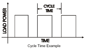
The APCMAN-1LP has one available cycle time of 350mS (@50%). Custom cycle times are available upon request.
The APCMAN-1LP is designed to provide the maximum control resolution and response time using a varied output cycle time. While the cycle time is specified at 350mS, this is at 50% power or 12mA input. As 4mA or 20mA is approached, the cycle time increases to limit the minimum on / off times to 100mS. This advanced approach maximizes the control resolution when the module is used with a zero cross fired SSR.
| |||||||||||||||||
|
4.2.2 Linearity |
|||||||||||||||||
| The control output linearity is +/-2% for the version without the zero and span potentiometers. Much tighter linearity can be achieved by adjusting the zero and span pots to optimize the linearity over the control range of the process. | |||||||||||||||||
|
4.2.3 Zero and Span Pots |
|||||||||||||||||
| The APCMAN-1LP can be ordered with Zero and Span pots as the APCMAN-1LP-ZS. This version allows the user to calibrate the low and high ends of the control range for the best possible linearity over the control range. It will also allow use of the module in load balancing applications and to skew the output response to meet specific needs. | |||||||||||||||||
|
4.3 Three Phase Operation |
|||||||||||||||||
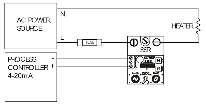
| One APCMAN-1LP can be used to control two poles of a three phase load using two SSRs with their control inputs wired in parallel. The Module should be wired as shown in the wiring diagram, but with separate load circuits for each leg. Make sure that the total input current requirements of the two SSRs can be achieved with the APCMAN-1LP. | |||||||||||||||||
|
4.4 Wiring of Multiple APCMAN-1LPs |
|||||||||||||||||
|
If more than one APCMAN-1LP is the be used from a single command signal, the command inputs should be wired in series, not in parallel.
| |||||||||||||||||
|
5 Electrical Specifications |
|||||||||||||||||
| |||||||||||||||||
|
Top of Page |
|||||||||||||||||
|
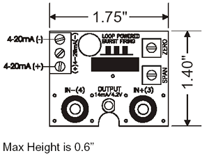
6 Mechanical Dimensions & Connection Diagram |
|||||||||||||||||
|
| |||||||||||||||||
| 7 APCMAN-1LP Wiring Diagram |
|||||||||||||||||
|
|
|||||||||||||||||
|
8 Contact Information |
|||||||||||||||||
|
Anacon Power & Controls 800-466-9080 www.anaconpower.com | |||||||||||||||||


