|
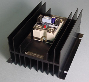
Anacon Power & Controls SCR Controller's are designed to offer proven solutions to both Phase Angle and Burst Fire applications. Our Phase Angle SCR Controllers operate by varying the firing point of an SSR's input. The power delivered to the load is proportional to the command input signal. SCR Controllers allow you to apply more precise control to any heater application, regardless of the type of heater elements you choose. |
|||||||||||||||||||||||||||||||||||||||||
|
Dimensions: 6.0" x 4.75" x 3.0" |
Standard Cool One Features:
|
||||||||||||||||||||||||||||||||||||||||
SPECIFICATIONS |
|||||||||||||||||||||||||||||||||||||||||
|
|||||||||||||||||||||||||||||||||||||||||
Notes:
|
|||||||||||||||||||||||||||||||||||||||||
|
|||||||||||||||||||||||||||||||||||||||||
MECHANICAL DRAWING |
|
||||||||||||||||||||||||||||||||||||||||
The APCSCR series are SCR Power Controllers (phase angle). The switch selectable control range for the PWM Input version is: 5-30V. The power delivered to the load is proportional to the command signal input. Input selection options are achieved by dip switch selection as noted above. The APCSCR Power Controller's PWM Input is designed to accept a signal from a PLC or a process/temperature controllers SSR drive output. A line to 24Vac transformer supplies power and phase information to the controller card. The transformer is connected across the AC power source as noted below. There is a feature to compensate for line voltage variation. By adjusting the phase angle automatically with line voltage changes, constant power is maintained at the load. To use the line voltage compensation feature properly, the 24Vac transformer should be fed from the same mains as the load circuit to be controlled per the wiring diagram per Figure 1. Line voltage compensation can be enabled or disabled via dip switch selections noted above. A separate control transformer is required for each APCSCR assembly. See User Manual for complete list of commands & wiring options. |
Figure 1 |
||||||||||||||||||||||||||||||||||||||||
©Copyright 2011 Anacon Electronic Sales, Inc.


